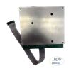
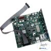
Jandy Large Back Board Power Interface PCB with Screws | R0467600
Jandy Large Back Board Power Interface PCB with Screws | R0467600
SKU#: R0467600
Jandy Power Interface PCB with Screws for AquaPure and ClorMatic Water Sanitizers
Write a Review

Jandy Large Back Board Power Interface PCB with Screws | R0467600
SKU# R0467600
Manufacturer: Jandy
Installation
SERVICE CODES
| Code Number | Possible Cause | Corrective Action |
| 124 | Higher than normal current to cell | 1. This is an indication of a bad back board.2. Troubleshoot with Jandy or a licensed professional. |
| 126 | Low current in forward direction and VAC input voltage below 100/200 VAC | 1. Check input voltage, transformer, and back board voltages.2. Troubleshoot with Jandy or a licensed professional. |
| 127 | Low current in reverse direction and VAC input voltagebelow 100/200 VAC | 1. Check input voltage, transformer, and back board voltages.2. Troubleshoot with Jandy or a licensed professional. |
| 170 | Possible Front board service condition or unit not correctly wired to 115 VAC | 1. Typically caused by low AC voltage from back board. Check the transformer and back board.2. Troubleshoot with Jandy or a licensed professional. |
| 171 | Possible backboard service condition | 1. Indication of a faulty board.2. Troubleshoot with Jandy or a licensed professional. |
| 189 | Relay not conducting in the forward direction. | Generates code 171- Back board service |
| 190 | Relay not conducting in the reverse direction. | Generates code 171- Back board service |
| 192 | High cell current and cell voltage falls below 19V. | Generates code 171- Back board service |
-
Product Details
About this product
Description
When your circuits are worn out or damaged, count on the Jandy R0467600 PCB Power Interface Replacement to get your control center running smoothly again. Keeping your power center in tip-top shape is vital for providing you and your family a pure water environment while hanging out in your swimming pool. Your control panel is running all operations, so it's important to always have well-functioning circuitry. This interface replacement circuit board is a power pack assembly replacement part for select swimming pool and spa power centers, allowing your electronic pool equipment to operate properly after malfunctions, extended use, or damage. This pool accessory part fits Jandy Purelink and ClorMatic which sanitize and purify your pool, providing a safe environment for swimmers. This Jandy R0467600 PCB Power Interface Replacement will get your Jandy power center back up and running in no time so you can spend less time worrying about your pool and more time enjoying it
Highlights
Installation
-
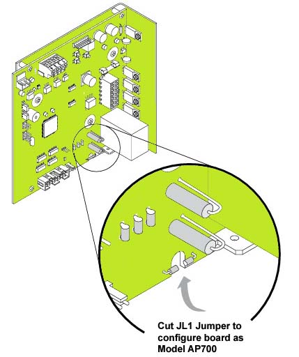
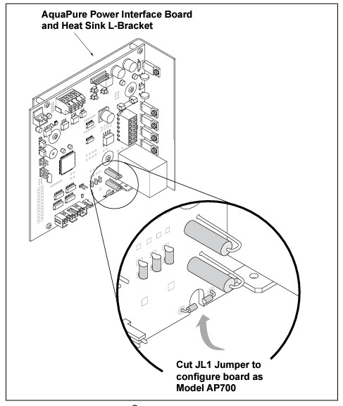
The AquaPure power interface board is configured as Model AP1400 by factory default. However, the power interface board can be configured as Model AP700.
To configure the board as Model AP700, use a cutting plier to cut the JL1 jumper as shown in Figure
- The power interface PCB part gets your pool and spa control center running smoothly
- Replacement for your existing circuitry that malfunctions is damaged, or is worn out
- A vital part of control panel operation
- It Fits Jandy Purelink and ClorMatic
- Easy to install with 2 included screws
Features
Installation
SERVICE CODES
Code Number Possible Cause Corrective Action 124 Higher than normal current to cell 1. This is an indication of a bad back board.2. Troubleshoot with Jandy or a licensed professional. 126 Low current in forward direction and VAC input voltage below 100/200 VAC 1. Check input voltage, transformer, and back board voltages.2. Troubleshoot with Jandy or a licensed professional. 127 Low current in reverse direction and VAC input voltagebelow 100/200 VAC 1. Check input voltage, transformer, and back board voltages.2. Troubleshoot with Jandy or a licensed professional. 170 Possible Front board service condition or unit not correctly wired to 115 VAC 1. Typically caused by low AC voltage from back board. Check the transformer and back board.2. Troubleshoot with Jandy or a licensed professional. 171 Possible backboard service condition 1. Indication of a faulty board.2. Troubleshoot with Jandy or a licensed professional. 189 Relay not conducting in the forward direction. Generates code 171- Back board service 190 Relay not conducting in the reverse direction. Generates code 171- Back board service 192 High cell current and cell voltage falls below 19V. Generates code 171- Back board service Brand Information

Build the perfect pool environment with Jandy professional-grade swimming pool equipment. With a full line of pumps, filters, heaters, lights, valves, water sanitizers, and the automation solutions to control it all, Jandy has the complete equipment package for any swimming pool or spa.
Visit Manufacturers Website -
-
Specifications
- Turn off all power to the power center.
- Open the door of the power center.
- Remove the top two (2) outer screws that secure the bezel plate assembly to the power center.
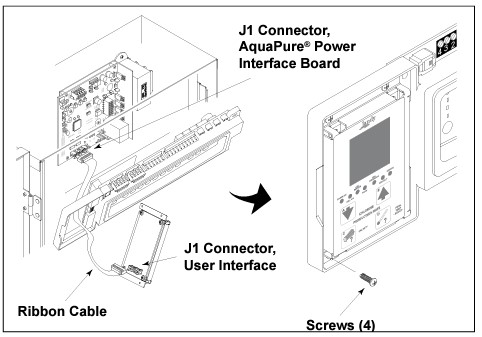
- Fold down the AquaLink® RS support plate and expose the AquaPure power interface board. See Figure .
- Disconnect the red four-pin connector from the red terminal bar located on the power interface board See Figure
- Disconnect the cable from the power interface board that leads to the user interface assembly.
- Disconnect the cable from the power interface board that leads to the AquaPure sensor.
- Disconnect the cable from the power interface board that leads to the transformer.
- Disconnect the DC wiring harness from the power interface board.
- Remove the two (2) center screws that secure the power interface board to the power center can. Remove the power interface board.
- Install the new power interface board and reconnect cables and connectors in reverse order.
-
Q/A
No Questions



Log in
Create a Free Account
Please fill out sign-up form
Sign up with your social media account
Or
Fill out sign up form
Why create an account
Sign up with your social media account