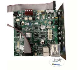
Jandy User Interface Board | R0467400
Jandy User Interface Board | R0467400
SKU#: R0467400
Zodiac R0467400 User Interface with 4 Screws Replacement for Select Zodiac Water Purification Centers
Write a Review

Jandy User Interface Board | R0467400
SKU# R0467400
Manufacturer: Jandy
Price:
$499.99
$499.99
Troubleshooting - Front Board
To help diagnose whether faults are occurring on the front board or with the
flow/salinity sensor three new test buttons have been added in the upper corner of
the front board.
They are:
– ‘R-Temp’
– ‘H-Temp’
– ‘Salinity’
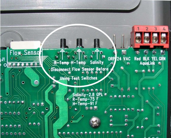
Disconnect the flow salinitytemp sensorfrom the front board. Press and hold the test buttons marked salinity and R-temp. While still pressing the test buttons press the ‘Salinity’key (‘C’) on the front cover of the unit. The LCD should read 2.8 gpl*.
While still holding the two front board test buttons press the ‘Pool Temperature’key (‘D’). It should read 75°F or 24°C.
Next, press and hold the board ‘H-Temp’test button, and at the same time press the ‘Salinity’key (‘C’) together with the ‘Chlorine Production Rate’arrow down key (‘A’) on the front cover of the unit. The LCD should read 91°F or 33°C.
If the readings are correct then the front board is O.K. and theproblem is with the flow sensor.
On the other hand if the readings are different then it indicates that there is a problem with the front board.
When the testing and repair is complete reconnect the flow sensor and reset the internal computer (do this by restarting the unit).
*Note: If the the salinity reading has been recalibrated this reading maybe different.
Before condemning the board check salinity setting.

-
Product Details
About this product
Description
Electrical Test on Front Board.
To read the front board AC voltage, test between “A” and “C” on the test strip that is in
the upper left hand corner of the front board. The AC voltage should be around 21 VAC.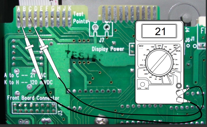
Highlights
Current test on front board
Note: - either the ‘Cell On’ or ‘Cell Reversing’ light must be lit during this entire test)
Test Cell Current Flow
To test the amperage going across the cell, you need to test the DC millivolts from K to H
The reading should be approximately 120 DC millivolts.
• 20 millivolts equal 1 ampere on a 1400 unit,
• 40 millivolts equal 1 ampere on a 700 unit.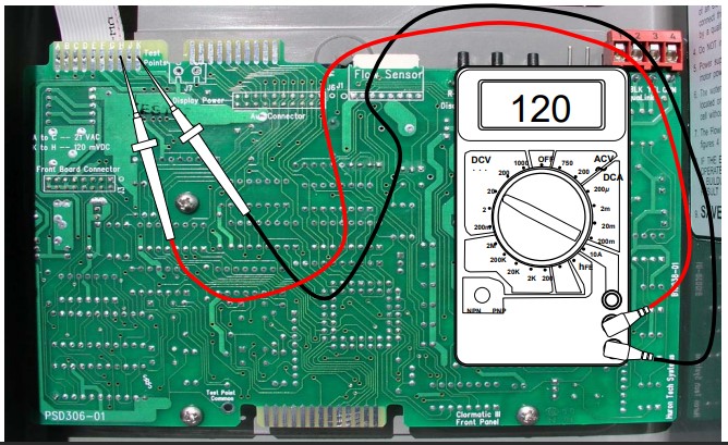
Features
Troubleshooting - Front Board
To help diagnose whether faults are occurring on the front board or with the
flow/salinity sensor three new test buttons have been added in the upper corner of
the front board.
They are:
– ‘R-Temp’
– ‘H-Temp’
– ‘Salinity’Disconnect the flow salinitytemp sensorfrom the front board. Press and hold the test buttons marked salinity and R-temp. While still pressing the test buttons press the ‘Salinity’key (‘C’) on the front cover of the unit. The LCD should read 2.8 gpl*.
While still holding the two front board test buttons press the ‘Pool Temperature’key (‘D’). It should read 75°F or 24°C.
Next, press and hold the board ‘H-Temp’test button, and at the same time press the ‘Salinity’key (‘C’) together with the ‘Chlorine Production Rate’arrow down key (‘A’) on the front cover of the unit. The LCD should read 91°F or 33°C.
If the readings are correct then the front board is O.K. and theproblem is with the flow sensor.
On the other hand if the readings are different then it indicates that there is a problem with the front board.
When the testing and repair is complete reconnect the flow sensor and reset the internal computer (do this by restarting the unit).
*Note: If the the salinity reading has been recalibrated this reading maybe different.
Before condemning the board check salinity setting.Brand Information

Build the perfect pool environment with Jandy professional-grade swimming pool equipment. With a full line of pumps, filters, heaters, lights, valves, water sanitizers, and the automation solutions to control it all, Jandy has the complete equipment package for any swimming pool or spa.
Visit Manufacturers Website -
Specifications

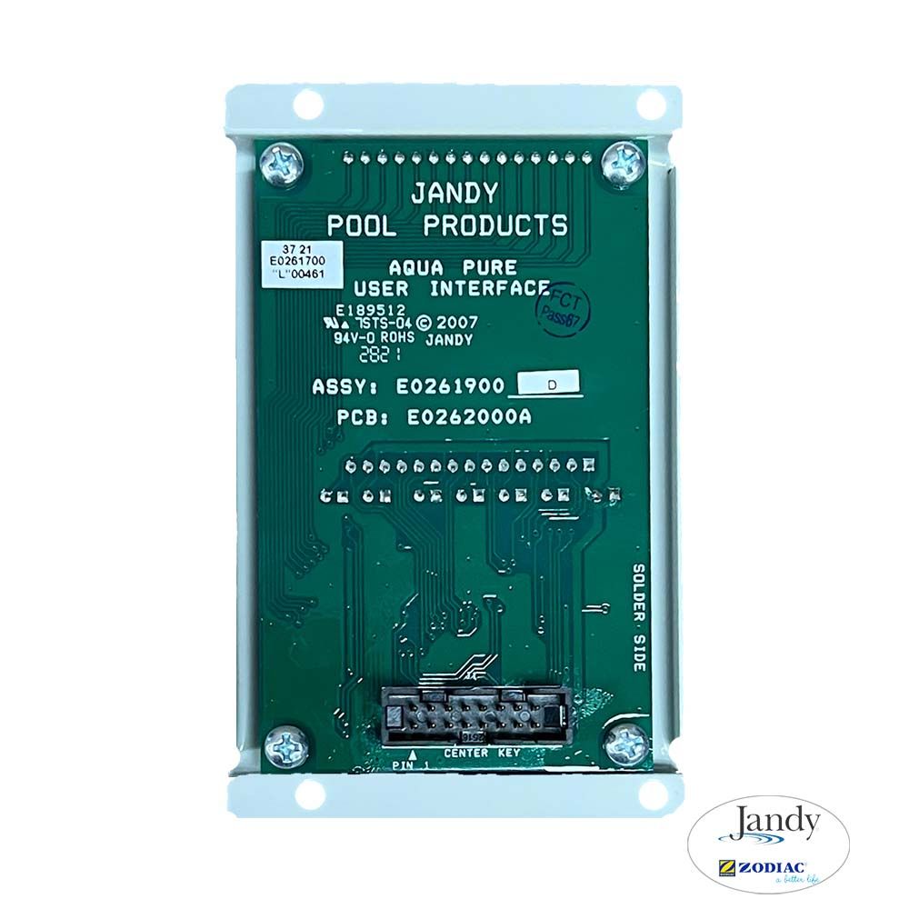
Installation of the Chlorine Generator User Interface Assembly into the
PureLink™ Power Center1. Turn off all power to the power center.
2. Open the door to the power center.
3. Remove the top two (2) middle screws that secure
the cover plate to the power center. Remove the
cover plate.4. Remove the four (4) screws the secure the user
interface assembly to the bezel. Remove the user
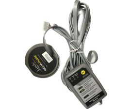
interface.5. Disconnect the ribbon cable (16-pin J1 connector)
from the back of the user interface board. See Figure .6. Install the new user interface assembly and reassemble in reverse order.

Installation of the Chlorine Generator User Interface Assembly into the Chlorine Generator Control Center
1. Turn off all power to the control center.
2. Open the door to the control center.
3. Remove the top two (2) screws that secure the cover plate to the control center. Remove the cover plate. See Figure .
4. Remove the four (4) screws that secure the user interface assembly to the mounting bracket.Remove the user interface.
5. Disconnect the ribbon cable (16-pin J1 connector) from the back of the user interface board. See Figure .6. Install the new user interface assembly and reassemble in reverse order.
-
Q/A
No Questions
Log in
Create a Free Account
Please fill out sign-up form
Sign up with your social media account
Or
Fill out sign up form
Why create an account
Sign up with your social media account