Jandy Power Distribution Circuit Board | R0458100
Jandy Power Distribution Circuit Board | R0458100
SKU#: R0458100
R0458100 Jandy Power Distribution Circuit Board LXI & JXI
Write a Review

Jandy Power Distribution Circuit Board | R0458100
SKU# R0458100
Manufacturer: ZODIAC
Price:
$134.99
$134.99
- Fits Jandy JXI400N, JXI400NK, JXI400NN, JXI260N, JXI260NK, JXI200N, JXI200NK, JXI400NC, JXI260NC Natural and JXI400P, JXI400PN, JXI400PK, JXI260P, JXI260PK, JXI200P, JXI200PK, JXI400PC, JXI260PC Propane Heaters.
- Also fits LXI250N, LXI250NN, LXI400N, LXI400NN, LXI250NC, LXI250NS, LXI400NC, LXI400NS Natural and LXI250P, LXI250PN, LXI400P, LXI400PN, LXI250PC, LXI250PS, LXI400PC, LXI400PS Propane Heaters.

-
Product Details
About this product
Description
- This Power Distribution Circuit Board Is Designed To Use With Zodiac Jandy Lxi Low NOx Pool And Spa Heater Models 250, 300, 400
- Power Distribution Circuit Board Replacement
- Fits Zodiac Janay Lexi Low NOx Pool And Spa Heater Models 250, 300, 400
Highlights
Jandy R0458100 Power Distribution Circuit Board fits on Models
JXI 200-400
LXI 250, 300, 400
Replacing the Power Distribution Board
1. Follow steps 1 and 2 in Section A.
2. Disconnect the wires connected to the distribution board and set them aside power.
Features
- Fits Jandy JXI400N, JXI400NK, JXI400NN, JXI260N, JXI260NK, JXI200N, JXI200NK, JXI400NC, JXI260NC Natural and JXI400P, JXI400PN, JXI400PK, JXI260P, JXI260PK, JXI200P, JXI200PK, JXI400PC, JXI260PC Propane Heaters.
- Also fits LXI250N, LXI250NN, LXI400N, LXI400NN, LXI250NC, LXI250NS, LXI400NC, LXI400NS Natural and LXI250P, LXI250PN, LXI400P, LXI400PN, LXI250PC, LXI250PS, LXI400PC, LXI400PS Propane Heaters.
Brand Information

Zodiac is a leading manufacturer of pool equipment, automatic pool cleaners & swimming pool accessories. Strives to deliver the perfect pool experience that enhances comfort, enjoyment, and peace of mind for pool owners.
Visit Manufacturers Website -
Specifications
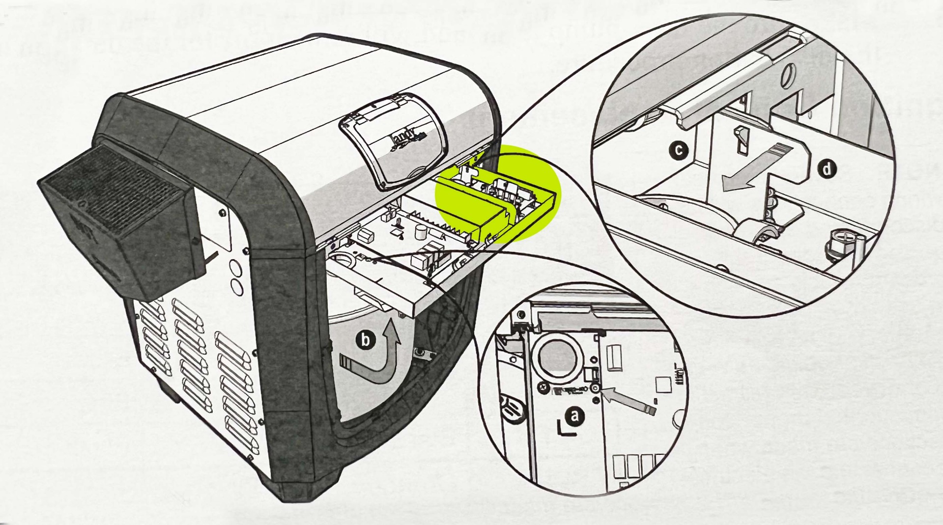
- Remove the four screws holding the front heater panel in place to expose the raceway.
- Locate the raceway lock release on the interior of the heater raceway
- Using a screwdriver or comparable tool; press into the raceway release orifice until the raceway latch releases, and the raceway swings free.
- Secure the raceway in place by lifting until the locking latch engages.
- Push the tab on the locking latch to the left to release.
Note : Before the raceway can be rotated for the first time a shipping zip tie must be cut. This zip tie is threaded at the raceway release point see item (a). While cutting this zip tie be sure not to damage or abrade any of the wires.
Shut Down :
- Turn off the electrical power to the heater
- Turn off the main gas supply to the heater at the meter or the manual gas valve outside the heater.
- Make sure the filter pump is off and will remain off for the duration of the installation procedure.
—-----------------------------------------------------------------------------
Power Distribution Board Replacement Jxi
- Locate the power distribution board on the exposed raceway (see Figure 2).
- Disconnect the 3 pin connector for the transformer (see Figure 4).
- Disconnect the 5 pin connector for the fan/blower (see Figure 4).
- Disconnect wires as indicated in Table 2. For Additional details, reference the wiring diagram on the heater front panel interior.
- Press tabs in to disengage the 4 plastic standoffs (see Figure 4).
- Remove the power distribution board (see Figure4).
- Discard of the removed power distribution board appropriately.
- Inspect and replace any damaged plastic standoffs with those included in the kit.
- Replace the power distribution board on the 4 plastic standoffs. Please refer to Figure 2 for proper orientation of the power distribution board on the raceway.
- Reconnect wiring according to table 2 and the wiring diagram located on the interior of the front heater panel. Be sure to pass the high voltage main power connection through the high voltage grommet on the raceway before reconnection to the main power leads.
Start Up :
- Restore electrical power to the heater
- Restore gas supply to the heater by opening the manual shut off valve outside the heater.
- Ensure that the filter pump is on and supplying adequate flow to the heater.
- Start the heater in either pool mode or spa mode. For more information please see the operating instructions label on the heater lid interior.
—-----------------------------------------------------------------------------
Power Distribution Board Replacement Lxi
Replaceing the power distribution board
- Follow steps 1 and 2 in section A
- Disconnect the wires connected to the power distribution board and set them aside.See Figure 1.
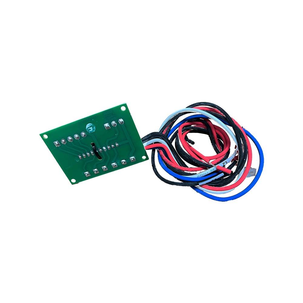
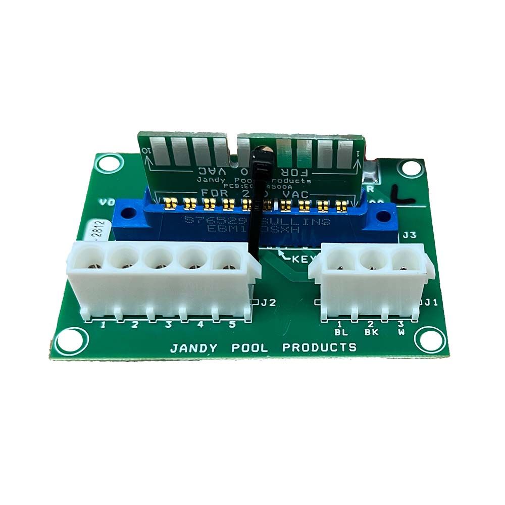
Note = The heater comes factory-wired intended for use with 240 volt, 60 hz AC field electrical supply. To use 120 volt, 60 Hz AC requires changing the position of the voltage selector board on the power distribution board as described below. ( This must be done by a certified electrician only, as with all wiring. Be sure that the power source to the heater is turned off or disconnected before servicing.)
- Cut the plastic wire tie that is holding the voltage selector board in place and discard the wire tie. Unplug the voltage selector board from the receptacle. See figure 2.
- Rotate the voltage selector board 180 degrees and reinsert it into the receptacle so that the hole in the board is not visible. Be sure that the board is securely seated in the receptacle.
Note = The voltage selector board is keyed so that it will fit in only one direction for either selected voltage ( either side of the board ).
3) Remove the power distribution board from the standoffs by compressing the standoff tabs that hold the power distribution board in place. See Figure 1.
4) If it is necessary to replace a missing or damaged standoff follow these steps :
- Remove the one (1) hex head screw from the control panel mounted to the burner panel.
- Remove the one (1) hex head screw from the control panel mounted to the door support.
- Remove the control panel by sliding the control panel to the right until the tabs slide out of the slots in the door support.
- Release the standoff from the back of the control panel and remove the standoff by puling it from the front of the control panel.
- Replace the standoff by pressing a new one into place from the front side of the control panel.
- Replace the control panel by sliding the control panel to the left until the tabs slide into the slots in the door support.
- Replace the one (1) hex head screw that mounts the control panel to the door support.
- Replace the one (1) hex head screw that mounts the control panel to the burner panel.
5) Attach the new power distribution board to the four (4) standoffs mounted to the control panel, align the standoffs to the mounting holes in the power distribution board, and press the board down until the standoffs snap into place.
6) Reconnect the wires and harnesses to the power distribution board. See Figure 3 on the last page.
7) Recheck the wiring schematic to make sure that the wiring is connected correctly. See Figure 3 on the last page.
-
Q/A
No Questions
Log in
Create a Free Account
Please fill out sign-up form
Sign up with your social media account
Or
Fill out sign up form
Why create an account
Sign up with your social media account