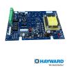
Hayward Main PCB E-Command 4 | GLX-PCB-HPC-4
Hayward Main PCB E-Command 4 | GLX-PCB-HPC-4
SKU#: GLX-PCB-HPC-4
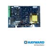
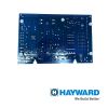
GLX-PCB-HPC-4 Hayward Main PCB Circuit Board For Hayward E-command 4 Automation Controls
Write a Review

Hayward Main PCB E-Command 4 | GLX-PCB-HPC-4
SKU# GLX-PCB-HPC-4
Manufacturer: HAYWARD
Hayward Heaters
Refer to the instructions in the heater manual for “2-wire Remote Thermostat” operation under “Remote
Control Connections” and the diagram on the below:
1. Turn off power to heater.
2. Wire Pro Logic to terminals 1 & 2 (see diagram).
3. Leave jumper attached to terminals 4 & 5.
4. Move “BYPASS” dipswitch on heater circuit board to “ON” position (up).
5. Turn heater power back on.
6. Switch heater to either “Pool” or “Spa” (it doesn’t make any difference which is selected, the Pro
Logic will take control).
7. Heater display should be “bO” (for “bypass On).
8. Heater will fire whenever Pro Logic requests (when Pro Logic “Heater” LED is illuminated).

-
Product Details
About this product
Description
Pentair/Purex/MiniMax
1. Turn power off to heater.
2. Remove factory installed jumper from the “Ext Switch” connector.
3. Wire the Pro Logic to the “Ext Switch” connector as shown below.
4. The wires to the Pro Logic must be separated from any line voltage wires. Failure to follow these
instructions may cause erratic operation of the heater.
5. Set the Power (Thermostat Select) switch to either “Pool” or “Spa”.
6. Set the “Pool” and “Spa” thermostats to their maximum settings.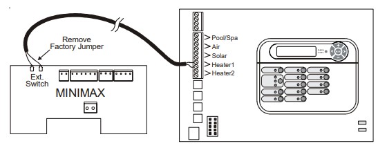
Highlights
Generic Heaters
1. Wire heater to 120/240V power source per the instructions in the heater manual. The Pro Logic does
NOT control the power going to the heater.
2. Wire the Pro Logic dry contact heater output per the diagram below. Many internal parts of the heater
can get very hot--see the heater manufacturer’s recommendations on the minimum temperature rating
for wires. If no guidance is given, use 105°C rated wire.
3. Set any ON/OFF switch on the heater to ON.
4. Set the thermostat(s) on the heater to the maximum (hottest) setting.
Laars Heaters
1. Turn power off to heater.
2. Remove factory jumper from terminal block.
3. Wire Pro Logic to the heater as shown.
4. Ensure toggle switch is in the ON position.
5. Set heater thermostats to maximum position.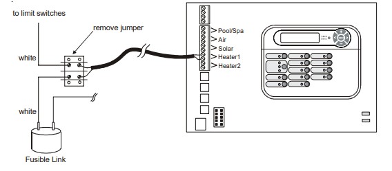
Features
Hayward Heaters
Refer to the instructions in the heater manual for “2-wire Remote Thermostat” operation under “Remote
Control Connections” and the diagram on the below:
1. Turn off power to heater.
2. Wire Pro Logic to terminals 1 & 2 (see diagram).
3. Leave jumper attached to terminals 4 & 5.
4. Move “BYPASS” dipswitch on heater circuit board to “ON” position (up).
5. Turn heater power back on.
6. Switch heater to either “Pool” or “Spa” (it doesn’t make any difference which is selected, the Pro
Logic will take control).
7. Heater display should be “bO” (for “bypass On).
8. Heater will fire whenever Pro Logic requests (when Pro Logic “Heater” LED is illuminated).
Brand Information

Hayward Industries, Inc. is the largest manufacturer of residential swimming pool equipment in the world. Headquartered in Elizabeth, New Jersey, Hayward designs and markets the Totally Hayward® System, a complete line of state-of-the-art, energy efficient residential pool equipment including pumps, filters, heaters, heat pumps, cleaners, electronic control systems, electronic chlorinators, lighting, safety equipment.
Visit Manufacturers Website -
Specifications
Raypak RP2100 Pool/Spa Heater
1. Turn power off to heater.
2. Push the mode button to “spa” mode.
3. Set the temperature to the maximum.
4. Push the mode button to “OFF”.
5. Lastly, plug the prewired connector in the P7 position on the board.
! IMPORTANT: The heater will display “OFF” when it is being remotely controlled by the
Pro Logic. Some homeowners see the “OFF” display and, thinking this is a mistake, change the
mode to “POOL” or “SPA” which then disables the remote control by the Pro Logic. To prevent
this: Remove the heater touch pad connector (P5) which will disable the touchpad.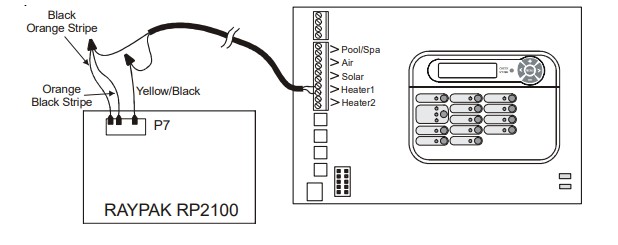
STA-RITE Heater
1. Turn power off to heater.
2. Remove upper jacket and open the control box.
3. Remove the jumper for the “fireman’s switch.
4. Wire to the Pro Logic using wire rated for 105°C minimum.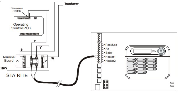
-
Q/A
No Questions



Log in
Create a Free Account
Please fill out sign-up form
Sign up with your social media account
Or
Fill out sign up form
Why create an account
Sign up with your social media account