Raypak, Transformer 115/230V-Kit | 006736F
Raypak, Transformer 115/230V-Kit | 006736F
SKU#: 006736F
Raypak Transformer 006737F
$77.99
Raypak Transformer Lid for use with Model:
- 185A
- 265A
- 335A
- 405A Pool Heaters
Raypak Transformer IID Electronic Heaters 120V-240V Kit with Wire Harness


-
Product Details
About this product
Description
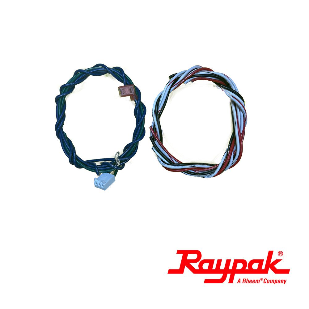
Raypak Heater Transformer that comes with the wire harness.
Features
Raypak Transformer Lid for use with Model:
- 185A
- 265A
- 335A
- 405A Pool Heaters
Raypak Transformer IID Electronic Heaters 120V-240V Kit with Wire Harness
Brand Information

For over 70 years, Raypak Raypak is a wholly owned subsidiary of Rheem Manufacturing and has been the world’s leading manufacturer of copper finned boilers and heaters. In 2000 Raypak’s primary manufacturing facility was relocated to a completely new 235,000 square foot building in Oxnard, California, its current headquarters. Raypak’s design goals are and have always been high quality, reliability and energy efficiency.
Visit Manufacturers Website -
Specifications
-
Replacement Procedures
- Determine whether incoming voltage to heater is 120 volts or 240 volts using a volt meter. Verify that heater has been bonded and grounded according to National Electric Code.
- Shut off main electrical power to heater.
- Turn power switch on heater to “off” position.
- Shut off gas supply to heater.
- Remove heater door.
- Locate electrical junction box or compartment that contains transformer. (See Figure 2 and 3). Location may be on inside on left side on older uits. On some models it is in a separate enclosure.
- Remove the screws that hold control cover in place.
- Disconnect wires from the existing transformer on both high voltage and low voltage sides.
- Remove existing transformer by removing screws and install new transformer using existing mounting screws.
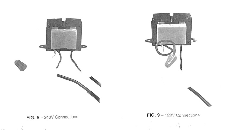
- Using wiring diagram in Fig 5, and two examples in Fig. 8 and Fig 9, wire high voltage side of transformer to incoming power to heater as determined in Step 1 above. NOTE : Incorrect wiring of the transformer at this point will damage the transformer and possibly other electrical components when power is applied.
- Turn on power temporarily and check secondary wires, blue and yellow. Voltage should be 24 to 28 volts AC.
- Turn off power.
- Connect low voltage wires (blue and yellow) into 24 volt circuit. Blue is the 24V hot and yellow is the 24V common. See Fig 4. Use the existing wiring diagram on the heater to determine correct connection points.

-
-
Q/A
No Questions
Log in
Create a Free Account
Please fill out sign-up form
Sign up with your social media account
Or
Fill out sign up form
Why create an account
Sign up with your social media account