Raypak Solid State Thermostat Control For Model 185B, 265B, 335B & 405B Millivolt Pool Heater | 005391F
Raypak Solid State Thermostat Control For Model 185B, 265B, 335B & 405B Millivolt Pool Heater | 005391F
SKU#: 005391F
Raypak Solid State Thermostat Control For Model 185B, 265B, 335B & 405B Millivolt Pool Heater
$239.99
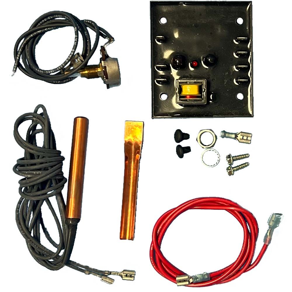
The solid state thermostat system consists of (3) major components: (1) control module, (1) temperature sensor, and potentiometers.
The following instructions have been separated into (3) sections:
SECTION 1 - Control Module Replacement
SECTION 2 - Temperature Sensor Replacement
SECTION 3 - Potentiometer replacement
Refer to wiring diagram below for reference during replacement.


-
Product Details
About this product
Description
IMPORTANT NOTICE
These instructions are primarily intended for the use of qualified personnel specifically trained and experienced in the installation of this type of heating equipment and related system components. Installation and service personnel may be required by some states to be licensed. Persons not qualified shall not attempt to install this equipment nor attempt repairs according to these instructions.
Follow the steps below, then proceed to replacement instructions.
1. Turn heater manual switch located in upper control panel to the "off" position.
2. Shut off gas supply & water supply to the heater.
3. Remove control panel as follows:
A. Remove lower door.
B. Remove (2) screws from bottom flange of control panel.
C. Slide down control panel to clear upper jacket panel.
4. Rotate control panel down until panel stops. Do not force.
NOTE: Caution must be taken not to damage controls or wiring.Features
The solid state thermostat system consists of (3) major components: (1) control module, (1) temperature sensor, and potentiometers.
The following instructions have been separated into (3) sections:
SECTION 1 - Control Module Replacement
SECTION 2 - Temperature Sensor Replacement
SECTION 3 - Potentiometer replacement
Refer to wiring diagram below for reference during replacement.Brand Information

For over 70 years, Raypak Raypak is a wholly owned subsidiary of Rheem Manufacturing and has been the world’s leading manufacturer of copper finned boilers and heaters. In 2000 Raypak’s primary manufacturing facility was relocated to a completely new 235,000 square foot building in Oxnard, California, its current headquarters. Raypak’s design goals are and have always been high quality, reliability and energy efficiency.
Visit Manufacturers Website -
Specifications
SECTION #1 CONTROL MODULE REPLACEMENT
1.Disconnect all wires that terminate at control module.
2.Remove control module from mounting bracket, and replace with new module.
3.Reconnect all wires to control module. Refer to wire diagram.NOTE: Wire connection to control module labeled " Valve (TH)", may be a black or blue wire depending
on date of manufacturer.SECTION #2 TEMPERATURE SENSOR REPLACEMENT.
1.Remove access panel on water connection side of heater.
2.Remove sensor retainer clip from well in the inlet/outlet header.
3.Disconnect sensor wires from control module labeled "SEN".
4.Remove sensor, and route sensor wires through the control box, cabinet holes, and retaining wire clips, to remove sensor from unit.
5.Insert new sensor into well and secure with new copper retainer clip provided in kit. Make sure new sensor in located at the bottom of the well.
6.Route sensor wires up through the «S" clip mounted over the edge of the cabinet, and through the white wire retainer next to the cabinet access hole. Make sure new sensor wires do not come in contact with the flue collector.
7.Route sensor wires through the access hole in the cabinet.
8.Connect sensor wires to control module labeled "SEN".
9.Reinstall access panel to heater.SECTION #3 POTENTIOMETER REPLACEMENT.
1.Disconnect wires from potentiometer at manual switch and control module.
2.Remove knob from potentiometer shaft.
3.Remove (2) screws that attach mounting bracket to control panel.
4.Remove hex nut and lock washer from potentiometer shaft.
5.Remove potentiometer from bracket.
6.Install new potentiometer to bracket. Insert tab on potentiometer into small hole next to large st hole. This will align rotation of potentiometer with the dial plate.
7. Insert lock washer, and secure with hex nut to bracket.
8. Attach mounting bracket to up-front control panel.
9. Connect short wire from potentiometer to manual switch.
10. Cut long wire from potentiometer to 6" and strip insulation back 1/4".
11. Crimp spade terminal provided to wire and connect to control module labeled "POT".
12. Reassemble up-front control panel to unit, and secure with (2) sheetmetal screws.
13. Install door unit, and secure with screw. -
Q/A
No Questions
Log in
Create a Free Account
Please fill out sign-up form
Sign up with your social media account
Or
Fill out sign up form
Why create an account
Sign up with your social media account