
Find your parts diagram
Sticker on the pump body (the part with the basket), not on the motor. Motor labels from Century, A.O. Smith or Regal won't match parts.
Label on the side of the tank near the base. Size is in sq ft, e.g. 420 sq ft = C4030 or CCP420.
Rating plate inside the front access panel. Note the BTU and gas type (NG or LP).
Molded into the body or printed on top. Robotic cleaners: on the power supply.
Still not sure? Call (818) 818-6559 and we'll find it for you.


HDXFCAP001 | Hayward Control Access Panel Assembly HDF Heaters
Fits these models
Pickup, delivery and shipping times are estimates, not guarantees.
Couldn't load pickup availability
● 19 in stock30-day returns Secure checkout
Have a question about this part?
Ask about fit, specs or shipping and get an instant answer.
Goes with this part
CA P65 Warning: Cancer and reproductive harm. www.p65warnings.ca.gov
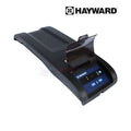
OEM Hayward Control Access Panel Assembly HDXFCAP001 is precision-designed for use with Hayward HC Series HDF400 heaters, offering secure protection for the heater’s internal control components. This durable panel serves as a reliable access point for maintenance and troubleshooting while shielding critical electronics from moisture, debris, and outdoor exposure. Made from weather-resistant, long-lasting materials, it’s built to withstand the harsh conditions common in pool equipment settings. Ideal for both original installations and part replacements, this OEM panel helps ensure stable, efficient heater operation.
-
Engineered for HDF400 Heater Models: OEM panel built specifically to enclose and protect controls in Hayward HC Series heating systems
-
Secure and Convenient Access Point: Provides a protective housing while allowing easy access to control components for servicing
-
Weather-Resistant and Durable: Constructed from high-quality materials to resist UV, moisture, and mechanical wear over time
-
Suitable for Installation or Replacement: Ideal for outfitting new systems or upgrading worn or damaged panels to restore protection
-
Maintains Heater Performance and Safety: Shields vital electronics from environmental damage to preserve system reliability and efficiency
- Compatible with Hayward HC Series HDF400 Heaters
1. Remove the single screw securing the top access panel to the cabinet
top
2. Lift the front lip of the top access panel several inches. The front of the
panel is where the user interface is located and the same side the
screw was removed from in step 1.
3. With the front of the top access panel elevated, slide the panel toward
the rear of the unit until the tabs holding the rear side down are disengaged from the cabinet top.
4. Carefully lift the top access panel free of the unit, ensuring excess
tension is not placed on the ribbon cable attached to the ignition control board inside the heater cabinet, and rotate it 180 degrees so that
the user interface is now on the opposite side of the heater.
5. Secure the top access panel to the heater in the new orientation by
installing the screw removed in Step 1 in the new location
