Jandy Union Kit for AquaPure 3 Port Cell | R0452100
Jandy Union Kit for AquaPure 3 Port Cell | R0452100
SKU#: R0452100
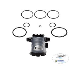
R0452100 Universal Union Replacement Kit for Jandy Pool and Spa Water Purification System
$49.99
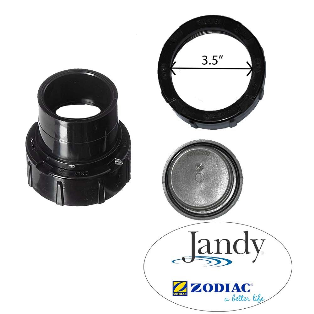
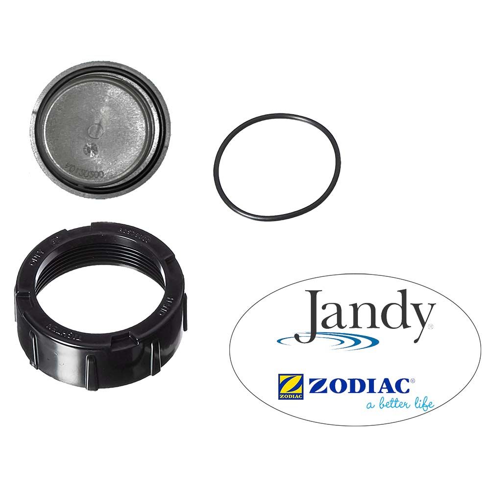
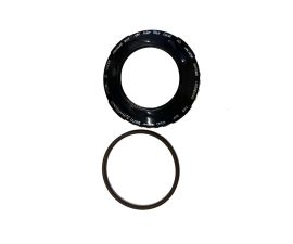
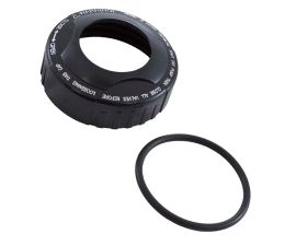
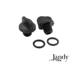
- Includes 3 universal union nuts, 3 o-rings, 2 tailpieces of 2-inch by 2-1/2-inch, 1 plug and port
- Also compatible with AquaPure , PureLink water purification system
- Fits Zodiac Jandy Nature2 Fusion soft and inground water purification system models FSOFT700, FSOFT1400,FUSION


-
Product Details
About this product
Description
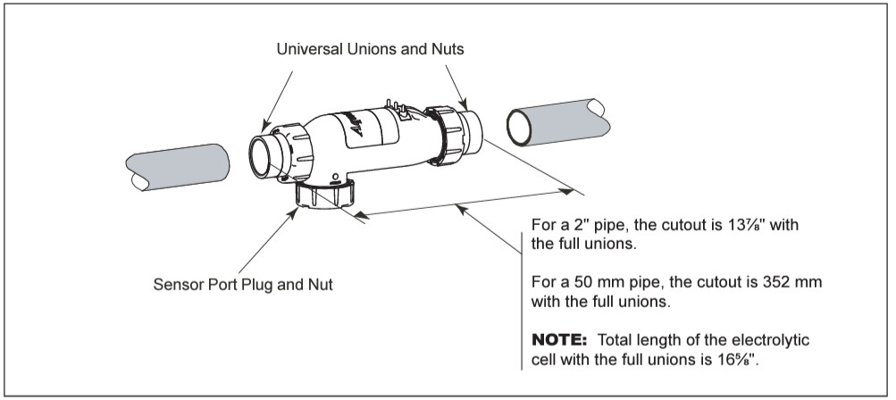
Replacement of Existing 3-Port Cell (Universal or 2” PVC Unions)
- Be sure pool pump is turned off.
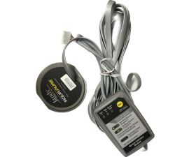
- Unplug DC cable from existing cell. Disconnect the DC cord from the wiring harness . Loosen the strain relief fitting that also contains the cable for flow/temp/salinity sensor. Pull the DC cord out through the strain relief.
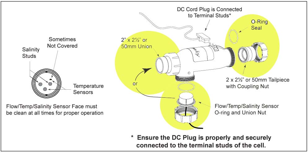
- Remove flow/temp/salinity sensor from cell by unscrewing coupling nut on sensor port. The sensor should pull straight out after nut is removed.
- Remove old 3-port cell body by unscrewing coupling nuts on flow ports. The cell body will be free to pull out after nuts are clear of the threads.
- Replace existing union o-rings with new o-rings provided with cell kit.
- Install new cell and tighten coupling nuts.
- Install the flow/temp/salinity sensor into the available sensor port.
- Plug the new DC cord provided with the cell kit, in either direction, into the cell stud terminals protruding from the cell top. Make sure that the plug is fully inserted and bottomed out on the housing.
- Connect the DC cord to the control center. Feed the DC cord through the same strain relief fitting as the flow/temp/salinity sensor. Plug the DC cord into the two spade connectors of the wiring harness.
- Tighten strain relief fitting screws for the flow/temp/salinity sensor cable and the DC cord. Do not pull flow/temp/salinity sensor cable or DC Cord too tight. Allow a little cable slack inside of control center enclosure.
- Check the wiring prior to reattaching front cover. Be sure the flow/temp/salinity sensor is plugged in. The DC cord should be plugged in. Also, check the AC wiring.
- If disconnected, plug the ribbon cable into the J1 connectors the user interface and the Power Interface PCB.
Highlights
Features
- Includes 3 universal union nuts, 3 o-rings, 2 tailpieces of 2-inch by 2-1/2-inch, 1 plug and port
- Also compatible with AquaPure , PureLink water purification system
- Fits Zodiac Jandy Nature2 Fusion soft and inground water purification system models FSOFT700, FSOFT1400,FUSION
Brand Information

Build the perfect pool environment with Jandy professional-grade swimming pool equipment. With a full line of pumps, filters, heaters, lights, valves, water sanitizers, and the automation solutions to control it all, Jandy has the complete equipment package for any swimming pool or spa.
Visit Manufacturers Website -
Specifications
Replacement of old 2-Port (Square) Cell with new 3-Port Cell
- Be sure pool pump is turned off.
- Unplug DC cable from existing cell. Disconnect the DC cord from the wiring harness as shown in Figure 2a, 2b, and 2c. Loosen the strain relief fitting that also contains the cable for flow/temp/salinity sensor. Pull the DC cord out through the strain relief.
- Please choose one of the following options (See Table 1):
3a. Option 1 - Retain Existing Sensor in Threaded Tee
3b. Option 2 - Install New Sensor in 3rd Port of Cell (remove old sensor and plug tee)
3c. Option 3 - Replace Section of Piping (eliminate old cell and sensor fittings) and treat as New Installation
2-Port Cell Thread Size and Style Option 1 Option 2 Option 2 2" PVC Male (black) Yes Yes Yes 1.5" ABS Female (White "Hayward®" Style) No No Yes
3a. Option 1 - Retain Existing Sensor in Threaded Tee
a. Remove old 2-Port cell body by unscrewing coupling nuts on ports. The cell body will be free to a. Remove old 2-Port cell body by unscrewing coupling nuts on ports. The cell body will be free to pull out after nuts are clear of the threads. b. Replace existing union o-rings with new o-rings provided with cell kit.
b. Replace existing union o-rings with new o-rings provided with cell kit. c. Install new cell and tighten coupling nuts.
c. Install new cell and tighten coupling nuts.
NOTE 3-Port Cell and 2-Port cell are the same length. The new cell should fit without any need to modify existing plumbing.
d. Ensure that the 3rd port is sealed off with provided o-ring, plug and nut. Verify coupling nut is d. Ensure that the 3rd port is sealed off with provided o-ring, plug and nut. Verify coupling nut is properly hand tightened.
e. Go to Step 4, below. e. Go to Step 4, below.
3b. Option 2 - Install New Sensor in 3rd Port of Cell (remove old sensor and plug tee)
a. Remove old flow/temp/salinity sensor by unscrewing it from the threaded tee. a. Remove old flow/temp/salinity sensor by unscrewing it from the threaded tee.
b. Replace sensor with 1 ½” threaded plug. b. Replace sensor with 1 ½” threaded plug.
c. Disconnect the flow/temp/salinity sensor from the Power Interface PCB as shown in c. Disconnect the flow/temp/salinity sensor from the Power Interface PCB as shown in Figure 2a, 2b, and 2c . Loosen the strain relief fitting that also contains the cable for the DC cord. Pull the flow/ temp/salinity sensor cable out through the strain relief.
d. Remove old 2-port cell body by unscrewing coupling nuts on ports. The cell body will be free to d. Remove old 2-port cell body by unscrewing coupling nuts on ports. The cell body will be free to pull out after nuts are clear of the threads.
e. Replace existing union o-rings with new o-rings provided with cell kit.
f. Install new cell and tighten coupling nuts. Install new cell and tighten coupling nuts. NOTE 3-Port Cell and 2-Port cell are the same length. The new cell should fit without any need to modify existing plumbing. g. Install the new flow/temp/salinity sensor into the 3-port cell (See Figure 11).
g. Install the new flow/temp/salinity sensor into the 3-port cell (See Figure 11).
h. Feed the connector end of the flow/temp/salinity sensor cable through the DC cord strain relief h. Feed the connector end of the flow/temp/salinity sensor cable through the DC cord strain relief fitting. Be certain the connector is clean and dry, then plug the cable into the connector on the Power Interface PCB as shown in Figure 2a, 2b, and 2c (Do not pull flow/temp/salinity sensor cable too tight, allow a little slack).
i. Go to Step 4, below. Go to Step 4, below.
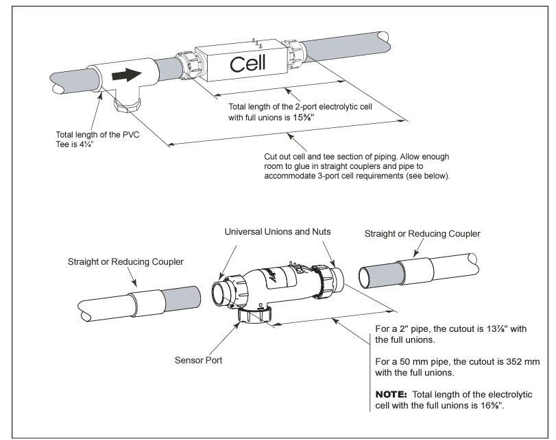
3c. Option 3 - Replace Section of Piping (eliminate old cell and sensor fittings) and treat as New Installation.
a. Cut out section of pipe that contains cell, sensor, and fittings. Glue straight couplers or reducing a. Cut out section of pipe that contains cell, sensor, and fittings. Glue straight couplers or reducing coupler onto open ends of piping. Make sure to leave enough length to fit in new cell (see Figure 13).
b. Go to Step 1, Section 3.7.1.New Installation - Plug the DC cord, in either direction, into the cell stud terminals protruding from the cell top. Make sure that the plug is fully inserted and bottomed out on the housing.
- Connect the DC cord to the control center. Feed the DC cord through the same strain relief fitting as the flow/temp/salinity sensor. Plug the DC cord as shown in Figure 2a, 2b, and 2c.
- Tighten strain relief fitting screws for the flow/temp/salinity sensor cable and the DC cord. Do not pull flow/temp/salinity sensor cable or DC Cord too tight. Allow a little cable slack inside of control center enclosure.
- Check the wiring prior to reattaching front cover. Be sure the flow/temp/salinity sensor is plugged in. The DC cord should be plugged in. Also, check the AC wiring.
- If disconnected, plug the ribbon cable into the J1 connectors the user interface and the Power Interface PCB (See Figures 2a, 2b, 2c, and 10).
-
Q/A
No Questions

Log in
Create a Free Account
Please fill out sign-up form
Sign up with your social media account
Or
Fill out sign up form
Why create an account
Sign up with your social media account