Jandy A0590804 SHPF and SHPM Pump 1.5 HP Impeller Replacement Kit| R0807201
Jandy A0590804 SHPF and SHPM Pump 1.5 HP Impeller Replacement Kit| R0807201
SKU#: R0807201
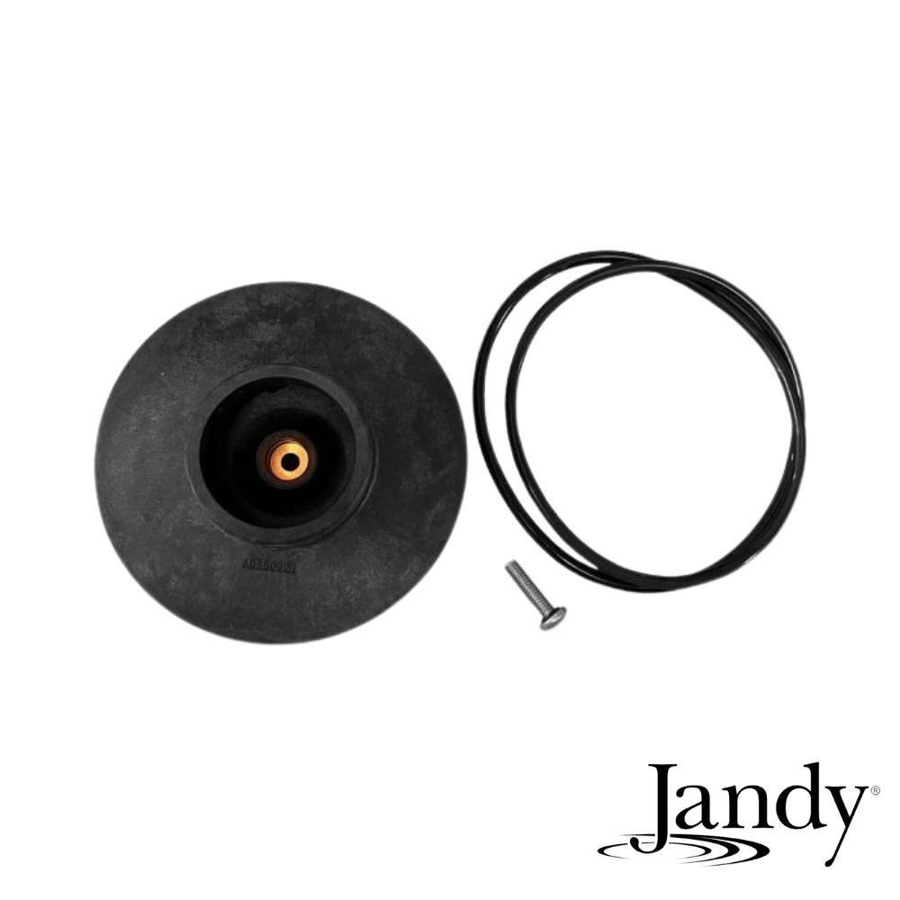
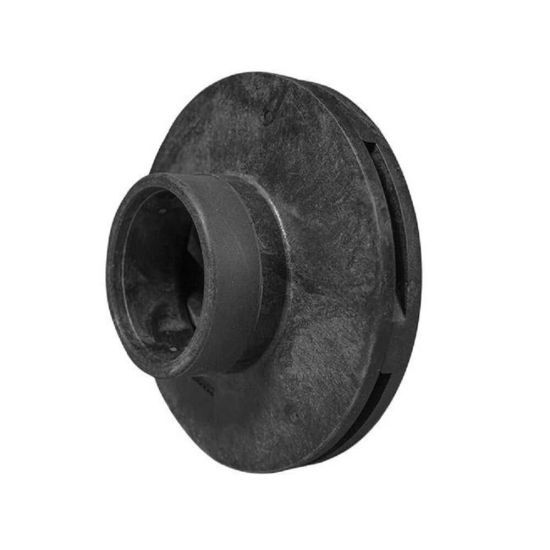
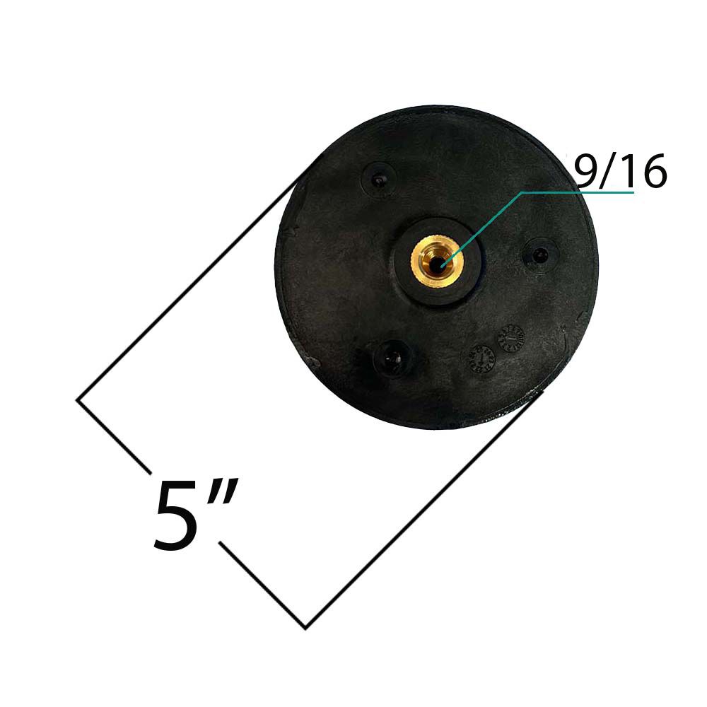
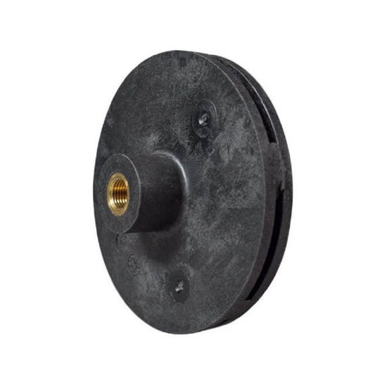
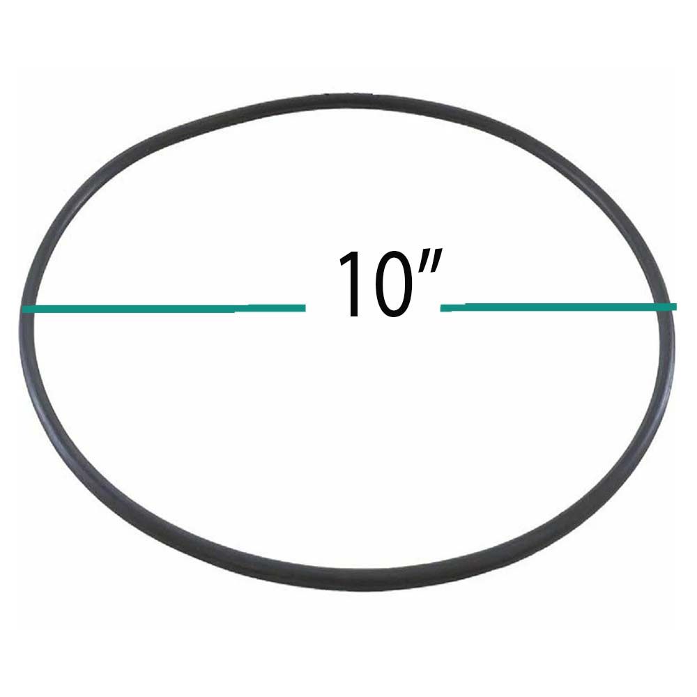
R0807201 Jandy 1.5HP A0580904 Impeller with Screw and Backplate O-Ring for Pro Series SHPF/SHPM Pumps
$56.99


-
Product Details
About this product
Description
Zodiac Pool Systems Inc, Jandy, Shp- Stealth/ Php-Plushhp, Impeller Kit, Horsepower: 1.5, For Use With:Epump(TM) Variable Speed Pump - Jep1.5, Jep2.0, Vsshp220, Vsshp270 / Stealth Series Pump - Shpf/Shpm / Plushp Series Pump - Phpf/Phpm,
Highlights
Features
Brand Information

Build the perfect pool environment with Jandy professional-grade swimming pool equipment. With a full line of pumps, filters, heaters, lights, valves, water sanitizers, and the automation solutions to control it all, Jandy has the complete equipment package for any swimming pool or spa.
Visit Manufacturers Website -
Specifications
Impeller/Diffuser and Hardware
Replacement
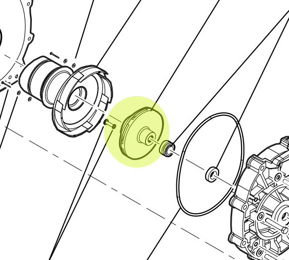
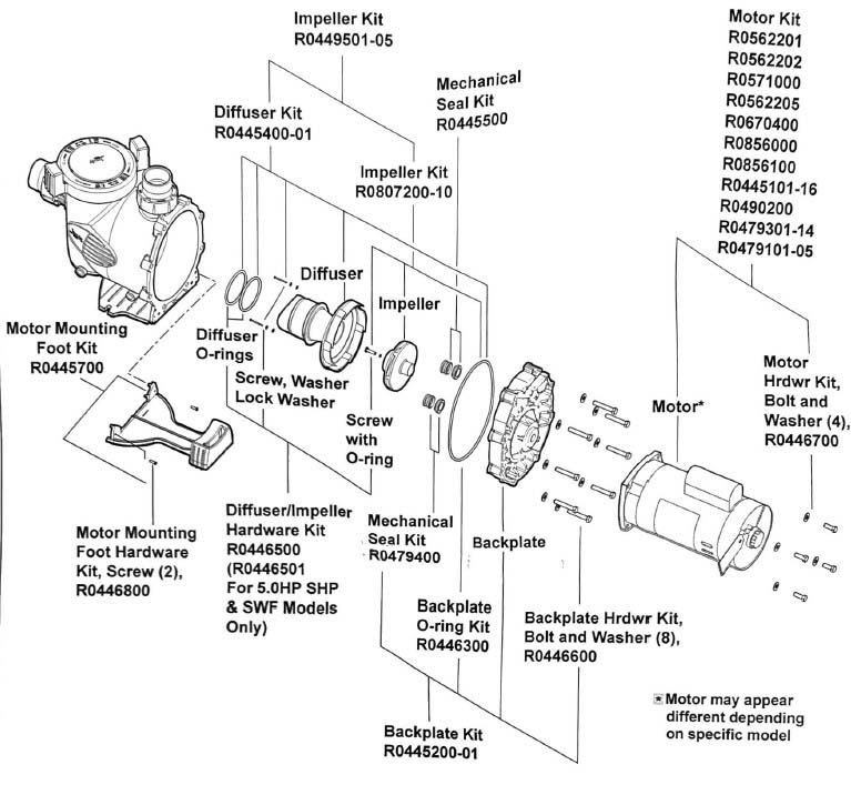
- Refer to Figures 2a and 2b and the associated parts list to identify the parts included in each replacement kit.
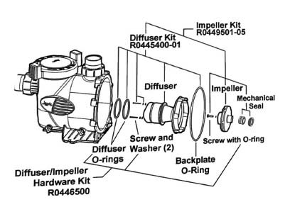
Figure 2a. Impeller and Diffuser Replacement Kits
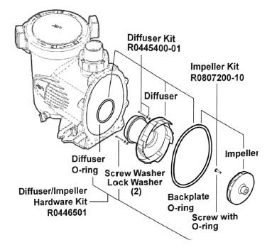
Figure 2b. Impeller and Diffuser Replacement Kits
- Using a No. 1 Phillips* screwdriver, remove the two (2) screws attaching the diffuser to the backplate. Carefully remove the diffuser from the backplate. See Figure 3.
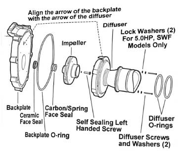
Figure 3. Impeller and Diffuser Assembly
- If necessary, remove any debris from the inlet and outlet of the impeller.
NOTE Disregard step 4 if your motor is a Variable Speed
Model.
- Remove the motor shaft cover on the back of the motor by twisting the hex-head screw with an adjustable wrench. The motor shaft will be exposed.
NOTE If the Impeller is not being replaced, please skip to
Step 9.
- Hold the exposed motor shaft with a ½' crescent wrench (5/16" allen wrench for Variable Speed Models) while removing the impeller center screw using a No. 2 Phillips screwdriver.
NOTE The impeller center screw is a left-hand threaded
screw. Therefore, turn the screw clockwise to loosen it.
- The impellor needs to be threaded off of the shaft (normal right-handed thread pitch) and the mechanical seal needs to be replaced.
NOTE An impellor wrench may be required to break the
impellor lose.
- While holding the motor shaft with a wrench, thread the new impeller onto the motor shaft.
Hand-tighten the impeller until it is secure.
- Using a No. 2 Phillips screwdriver, tighten the impeller's center screw into the center of the impeller. Do not over-tighten. Spin the impeller by hand after installing it, confirming that it will spin freely, without binding.
NOTE The impeller's center screw is a left-hand threaded
screw. Therefore, turn the screw counter-clockwise to tighten it.
- Replace the motor shaft cover by inserting the cover tabs into the slots and rotating the cover 90° clockwise. (Disregard this step for variable speed pumps.)
- Install the new diffuser over the impeller using care to insert the alignment pins into the correct holes. The molded-in arrow must align with the molded-in arrow on the backplate. See Figure 3.
- Install the two (2) Phillips-head screws and washers. Tighten the screws to draw the diffuser against the backplate. For 5.0HP, SWF models only, use additional lock washers. See Figure 3.
NOTE Rotate the motor shaft by using the appropriate
wrench, ensuring that the motor will turn freely after the installation of the diffuser. If the components are not aligned correctly, you will hear the impeller scraping on the diffuser.
- Make sure the diffuser o-rings, o-ring grooves, and o-ring seal areas are clean and free of debris, which could cause a leak. If grease is used to retain the o-rings, it must be silicone based. Do not use petroleum-based grease, because it will destroy the o-rings.
- If you are not installing another replacement kit, skip to Section 7, Pump Assembly, to reassemble the pump.
- Backplate, Hardware and Mechanical Seal Replacement
Refer to Figure 4 and the associated parts list to identify the parts included in each replacement kit
-
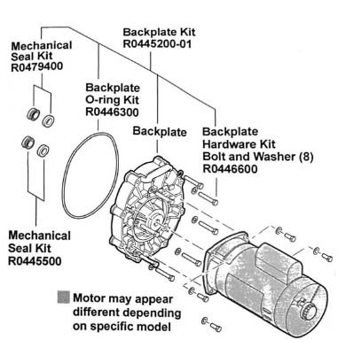
Figure 4 Backplate, Hardware, and Seal Replacement Kits
The impellor needs to be threaded off of the shaft (normal right-handed thread pitch) and the mechanical seal needs to be replaced. While holding the motor shaft with a wrench, thread the new impeller onto the motor shaft. Using a No. 2 Phillips screwdriver, tighten the impeller's center screw into the center of the impeller. Do not over-tighten. Spin the impeller by hand after installing it, confirming that it will spin freely, without binding. Replace the motor shaft cover by inserting the cover tabs into the slots and rotating the cover 90° clockwise. (Disregard this step for variable speed pumps.) -
1.Disassemble Backplate and Impeller
Using a No. 1 Phillips screwdriver, remove the two (2) screws attaching the diffuser to the backplate. Carefully remove the diffuser from the backplate and remove any debris from the inlet and outlet of the impeller.
- Remove the motor shaft cover on the back of the motor by twisting the hex-head screw 90°
with a crescent wrench. The motor shaft will be exposed.
NOTE Disregard step 2 if your motor is a Variable Speed
model.
- Hold the exposed motor shaft with the wrench while removing the impeller center screw using a No. 2 Phillips screwdriver.
NOTE The impeller screw is a left-hand threaded screw.
Therefore, turn the screw clockwise to loosen it.
- Hold the motor shaft with the wrench while unscrewing the impeller from the motor shaft with your hand.
NOTE The impeller is a right-hand thread. Therefore, turn it
counter-clockwise to unscrew it.
- Remove the impeller from the backplate and motor shaft
-
Q/A
No Questions
Log in
Create a Free Account
Please fill out sign-up form
Sign up with your social media account
Or
Fill out sign up form
Why create an account
Sign up with your social media account